
Modular Rack Fan Controller
by Austin's Creations
I2C compatible board that handles Rack Fan control to keep your racks running COOL
Designed to be assembled in a modular format so multiple boards can easily fit next to each other
This board allows for the control of 8 fans. It can control 3-4 wire fans that are mounted within an enclosure. the fans are connected to breakouts within a case, and each breakout uses and RJ45 socket. that links to a main controller that has an 8 port RJ45 socket
Features
- Each Board Controls 8 fans - Expandable to 64 fans (8 boards)
- TCA9548A I2C MUX chip - giving the system expandability
- EMC2101 Fan control chip (one on each TCA i2c line)
- 6 pin IDC connection for easy linkign to rack32 or room8266 or OXRS Black or other compatible controller
- support to control a fan that the board itself is mounted in
- offered breakout has onboard temp sensor, and purcase can include 30mm square 4 wire 5v fan
- each port fuse at 500mA
Using the product
Using your Rack Fan Controller board is a fairly strightforward process. each board has a set of screw terminals. These are for your 12-24v power input (12v is the recommended option). There are two terminals to allow for easy daisy chaining between other boards. The board Doesn't use power input on IDC connector.
When using the on board fan connector - located above the right side IDC conection. Add a jumper to the two set pin header. This enables the Temp sensor for that port. Using the onboard connection disables port 8 on the RJ45
Don't hot swapping your I2C cable
The 2*3 pin 2.54mm IDC cable isn't recommended to be removed or added when the system is powered, turn off power before changing things
There are a totally of 2 DIP switches built into the Board. The one on the right top is labeled length wise along itself I2C P/U this is for your I2C pullup resistors. The device that is the furthest away from the main rack controller should have this enabled. (both pin turn on)
The other DIP switch is 4 pins. The lowest pin - closest to the 8 port RJ45 is the RST this connects the TCA to the main controller RST line. These should be on, but can be turned off when trying to solve debug problems
The other three positions on those 4 position DIP switches are for setting the TCA address. Up to 8 TCAs can be on an I2C bus but they each need their own address, position 0 starts at the top of the PCB
| Position | 0X70 | 0X71 | 0X72 | 0X73 | 0X74 | 0X75 | 0X76 | 0X77 |
|---|---|---|---|---|---|---|---|---|
| 0 | off | on | off | off | on | on | off | on |
| 1 | off | off | on | off | on | off | on | on |
| 2 | off | off | off | on | off | on | on | on |
The ports are numbered:
| Top | 1 | 3 | 5 | 7 | |
| Bottom | 2 | 4 | 6 | 8 |
From looking at the ports in front of an assembly like it would look installed in a rack case
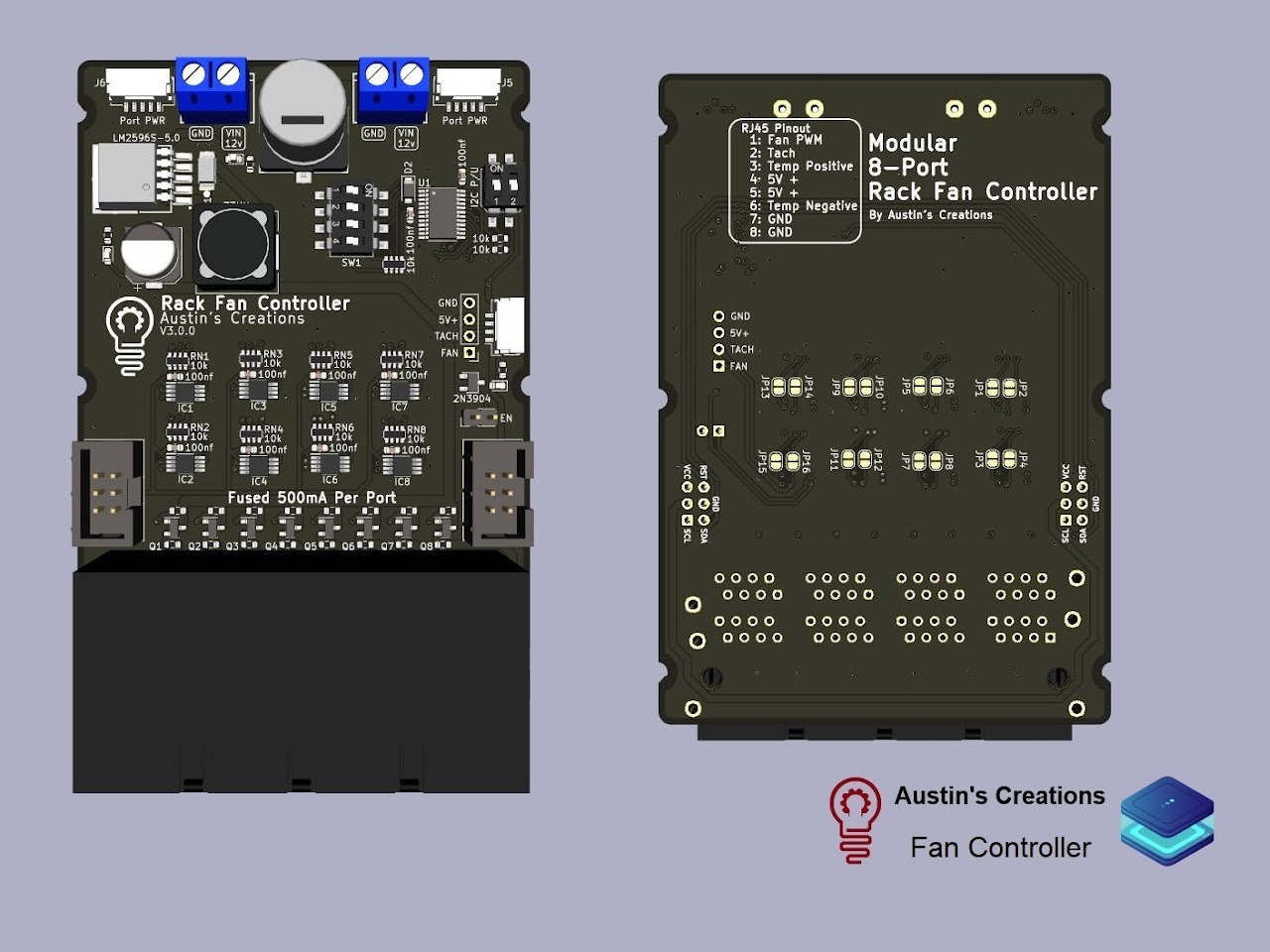
Each Port has 8 pins they breakout as follows:
| 1 | 2 | 3 | 4 | 5 | 6 | 7 | 8 |
|---|---|---|---|---|---|---|---|
| Fan PWM | Tach | Temperature Positive | 5V + | 5v + | Temperature Negative | GND | GND |
Library
- Fan Control library on Github
Supported Firmware
- Fan Controller firmware on Github <-- Firmware incomplete -->
- Power Distribution Unit (PDU) firmware on Github
Additional Resources
- Schematics and design files on Github
Where to Buy
- Contact on Discord or website