
Modular-Security-I2CRJ45
by Austins Creations
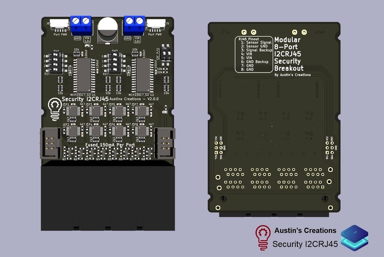
I2C compatible module that handles EOL Security monitoring.
Designed to be assembled in a modular format so multiple boards can easily fit next to each other.
Features
- Comes with 8 ports
- Expandable up to 32 ports
- Firmware supports Normal, Alarm, Tamper, Short, Fault
- 12-24v DIY POE on the RJ45 connections
- 1 input per port
- Per port power switching via external DIP switches
- Each port has a 150mA poly fuse
- Will fit side by side in the same space as a normal I2CRJ45 board from SuperHouse
Using the product
Using your Modular Security I2CRJ45 board is a fairly strightforward process. Each board has a set of screw terminals. These are for your 12v power input (The board is 24v tolerant but won't work on 24v). There are two terminals to allow for easy daisy chaining between other boards. The board doesn't use power from the IDC connector. Only VCC (logic voltage; commonly 3.3v with the rack32 / oxrs black) is connected from the IDC connector.
Don't hot swapping your I2C cable
The 2*3 pin 2.54mm IDC cable isn't recommended to be removed or added when the system is powered, turn off power before changing things.
There are a total of 3 DIP switches found on the board. The one on the top-right is labeled length wise along itself I2C P/U this is for your I2C pullup resistors. The device that is the furthest away from the controller should have this enabled.
The other two DIP switches are 4 pin. The lowest pin, closest to the 8 port RJ45 block, is the RST. This connects the MCP (the one to the right of each DIP) to the main controller RST line. These should be on, but can be turned off when trying to debug issues.
The other three positions on these 4 position DIP switches are for setting the MCP addresses. Up to 8 MCPs can be on an I2C bus but they each need their own address, position 0 starts at the top of the PCB.
| Position | 0X20 | 0X21 | 0X22 | 0X23 | 0X24 | 0X25 | 0X26 | 0X27 |
|---|---|---|---|---|---|---|---|---|
| 0 | off | on | off | on | off | on | off | on |
| 1 | off | off | on | on | off | off | on | on |
| 2 | off | off | off | off | on | on | on | on |
The ports are numbered (when viewing the RJ45 block from in front):
| Top | 1 | 3 | 5 | 7 | |
| Bottom | 2 | 4 | 6 | 8 |
Each Port has 8 pins and they breakout as follows:
| 1 | 2 | 3 | 4 | 5 | 6 | 7 | 8 |
|---|---|---|---|---|---|---|---|
| Sensor Signal | Sensor GND | Sensor Backup | VDD | VDD | Sensor Backup GND | GND | GND |
| orange/white | orange | green/white | blue | blue/white | green | brown/white | brown |
| green/white | green | orange/white | blue | blue/white | orange | brown/white | brown |
VDD is your system voltage; AKA the power being fed by the screw terminals (12-24v).
Sensor Backup is NOT a second sensor input, but rather a repeat of the first sensor attached to pins 1 and 2. Under normal uses the wire shouldn't be touched. It is there as a backup should your first set of wires be broken. It could possibly save you from having to immediately having to run new wire.
Wiring up a sensor requires a 10k and a 4.7k resistor. Wired as follows: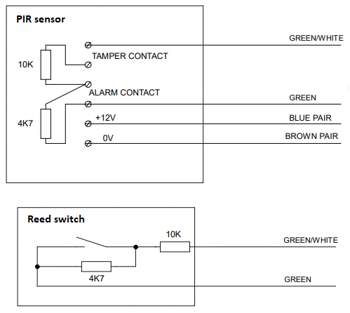
Supported Firmware
Additional Resources
- More info Github
Where to Buy
- Contact on Discord or WEBSITE