
Security Monitor ESP32
by Ben Jones
SKU: OXRS-AC-SECURITYMONITOR-ESP32-FW
Introduction
A security sensor monitor for DIY home automation projects.
This system uses UTP cable (typically Cat-5e because it's cheap) to connect sensors to a central controller. The sensors can be reed sensors attached to doors or windows, PIR sensors for motion detection, or anything else that reports a digital state.
How does it work?
When a sensor state change is detected an MQTT message is published to the configured MQTT broker for further processing by your home automation system.
Devices such as PIR sensors or door/window reed switches can be connected to provide a high level of security and ensure you are alerted if there is any tampering to the sensor or wiring (whether intentional or not), as well as reporting the sensor state.
The security monitor will report one of 5 states for each connected device. It achieves this by using two end-of-line (EOL) resistors connected to each security sensor.
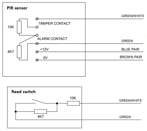
Resistor 1 (10K) is connected in series with the security alarm wiring, and resistor 2 (4K7) is connected across the alarm contact.
The firmware will detect and report the following states for a security sensor wired up with EOL resistors;
| State | LCD Display | Description |
|---|---|---|
| Normal | Green | The sensor is in a safe state, e.g. no movement detected or door/window is closed |
| Alarm | Red | The sensor has been tripped, e.g. movement detected or door/window is opened |
| Tamper | Magenta (flashing) | The sensor wiring has been compromised (open circuited), e.g. a sensor cover has been removed or a cable has been cut |
| Short | Magenta (flashing) | The sensor wiring has been compromised (shorted), e.g. intentional attempt to bypass the sensor, or a nail/screw through the cable |
| Fault | Cyan (flashing) | The sensor has been unplugged or a system fault has been detected |
The firmware is designed to run on hardware using MCP23017 I/O buffer chips via I2C, e.g. the Security Module.
Configuration
The firmware can be configured by publishing an MQTT message to this topic;
[PREFIX/]conf/CLIENTID[/SUFFIX]
where:
PREFIX: Optional topic prefix if requiredCLIENTID: Client id of device, defaults to<MACADDRESS>SUFFIX: Optional topic suffix if required
The message payload should be JSON and it's format is defined in a JSON schema document included in the adoption payload published here;
[PREFIX/]stat/CLIENTID[/SUFFIX]/adopt
See the config value in the /adopt payload.
TIP
This firmware works in a similar way to the State Monitor, but with all ports set to type "security".
Port Config
Each PORT can be configured via the following properties;
| Key | Mandatory | Value |
|---|---|---|
port | Mandatory | Index of the port to configure |
invert | Optional | Either true or false |
disabled | Optional | Either true or false |
WARNING
Disabling a port will stop any events being emitted!
Examples
To configure port 4 to be inverted, and port 8 to be disabled;
{
  "ports": [
    { "port": 4, "invert": true },
    { "port": 8, "disabled": true }
  ]
}
TIP
A retained message will ensure the device auto-configures on startup.
Events
A port EVENT is reported to a topic of the form:
[PREFIX/]stat/CLIENTID[/SUFFIX]
where;
PREFIX: Optional topic prefix if requiredCLIENTID: Client id of device, defaults to<MACADDRESS>SUFFIX: Optional topic suffix if required
The message payload is JSON and contains:
| Key | Value |
|---|---|
port | Port this event occured on (1-32) |
type | Event type (always security) |
event | Event (see below) |
| Event Type | Event |
|---|---|
security | normal, alarm, tamper, short or fault |
Examples
A contact sensor opening on port 2;
{
  "port": 2,
  "type": "security",
  "event": "alarm"
}
A short detected on port 4;
{
  "port": 4,
  "type": "security",
  "event": "short"
}
Supported Hardware
This firmware is compatible with the Security Module and is designed to run on the RACK32 as part of the OXRS eco-system.
The Security Module hardware provides 12V power down the cable, which can be used for powering sensors (e.g. PIRs).
The sensor needs to have EOL resistors installed, or alternatively you can use an EOL Sense RJ45 breakout from Bedrock Media Designs, which has the EOL resistors built-in and provides easy-to-use screw terminals for connecting your sensor to.
The RJ45 pinout for each port is;
| PIN | DESCRIPTION |
|---|---|
| 1 | SENSOR |
| 2 | SENSOR CMN |
| 3 | SPARE |
| 4 | VIN |
| 5 | VIN |
| 6 | SPARE CMN |
| 7 | GND |
| 8 | GND |
Further Information
Downloads
Download the latest binary of the firmware from GitHub.
Download the source code of the firmware from GitHub.
Home Automation Integration
Below are some examples of how you could integrate with various home automation systems.
Home Assistant integration examples.
Node-RED integration examples.
Credits
- Frank McAlinden frankmc@internode.on.net
- Austin's Creations https://www.austinscreations.ca
- Ben Jones https://github.com/sumnerboy12
- Moin https://github.com/moinmoin-sh
License
Copyright 2020-present Austin's Creations https://www.austinscreations.ca
The software portion of this project is licensed under the Simplified BSD License. The "licence" folder within this project contains a copy of this license in plain text format.