
ESP32 LCD library
by OXRS Core Team
SKU: OXRS-IO-LCD-ESP32-LIB
Introduction
This library serves a common status display for OXRS compatible controller with a LCD.
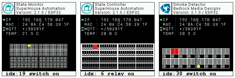
The screen shots above show examples for
- State Monitor (input only, 128 inputs, switches, buttons, ...)
- State Controller (output only, 128 outpus, relays)
- Smoke Detector (input and output, 16 inputs, 32 outputs, special use case smoke detector)
For most of the fields the displayed information is the same for all three different I/O-boards, except the port animation is dedicated to the specific I/O.
The header shows the maker logo together with FW related information (details on the logo are below).
The second block shows
- IP-address of the device. The virtual LED to the left shows the IP link status up/down in green/red. Self discovered by the lib.
- MAC address of the device. Self discovered by the lib.
- Wildcard MQTT topic for publish and subscribe. The two virtual LEDs to the left show MQTT activity (RX top, TX bottom) and flash when a message is received or sent. Self discovered by the lib.
- Temperature. The value shown has to be supplied and updated periodically by the FW. The lib serves an API call
OXRS_lcd::show_temp (float temperature)for this purpose. E.g. the RACK32 controller uses this for on-board temperature monitoring.
The third block shows the port animation. The layout of this field depends on the I/O-board and it's functionality. The lib reads the I/O-pins of the MCP23017 I/O-expander chips on the I/O-boards in it's loop() and reacts on any change by changing the shape and/or color of the associated virtual LED. Input LEDs are shown in yellow, output LEDs are shown in red if active. Not detected MCP23017 chips are indicated by a gray outline.
The bottom row is reserved to show events published over MQTT. The latest event is shown for 3 seconds and the display dimms after 10 seconds of inactivity (defaults)
Configuration
General
This library is designed to support a ST7789 based 240x240 pixel display.
It requires the TFT_eSPI library by Bodmer to be installed and configured for the target MCU + display.
You can install this library a number of ways;
- Install via Arduino Library Manager (search for
TFT_eSPI) - Install via PlatformIO (using
bodmer/TFT_eSPI) - Download original version from GitHub
The following configuration is required;
USER_SETUP_LOADED=1

ST7789_2_DRIVER=1

TFT_RGB_ORDER=TFT_RGB

TFT_WIDTH=240
TFT_HEIGHT=240

TFT_MOSI=23
TFT_SCLK=18
TFT_CS=25
TFT_DC=2
TFT_RST=4
TFT_BL=14

SPI_FREQUENCY=40000000

LOAD_GLCD=1   ; Font 1. Original Adafruit 8 pixel font needs ~1820 bytes in FLASH
LOAD_FONT2=1 	; Font 2. Small 16 pixel high font, needs ~3534 bytes in FLASH, 96 characters
LOAD_GFXFF=1  ; FreeFonts. Include access to the 48 Adafruit_GFX free fonts FF1 to FF48 and custom fonts
You can specify these in your PlatformIO build file (platform.ini) or if using the Arduino IDE you will need to create a custom setup file and place in the \User_Setup folder of the TFT_eSPI library folder in your Arduino library. See the TFT_eSPI Github repo for instructions on how to configure this.
Maker logo displayed on LCD
This lib has the ability to display a maker supplied logo in the top/left corner of the LCD.
The reserved space for a logo is 40 pixel high and 40 pixel wide at the top/left corner of the LCD.
- A larger logo will be cropped starting with the bottom/left corner of the .bmp.
- A smaller logo will be displayed starting at the bottom/left position of the reserved space.
Create your own logo
The first step to create your own logo is to prepare a 40x40 pixel 24-bit-bitmap file (.bmp). Use your choice of image processing tool. If you have an image file already from which you want to use an extract, you need to
- create/crop a quadratic extract of the desired content (width = height).
- change the image size to 40 x 40 pixel and save it as 24-bit-bitmap file named logo.bmp.
Deploy logo from SPIFFS
To use this method upload the logo.bmp file to the SPIFFS of your target MCU. If you are using the Arduino IDE, copy your logo.bmp to the data folder of your sketch and use ESP32 Sketch Data Upload from the tools menu to upload everything located in the data folder.
Deploy logo embedded in FW binary
Using this method embeds your maker logo in the binary of your sketch. This guaranties the availability of your logo at runtime independent of the availability of the SPIFFS and without having to do the extra upload.
Following steps are required:
- convert your
logo.bmpto a C header file using theconvert.pyscript supplied in the tools folder of the lib - copy
logo.hinto your sketch folder - include
logo.hin your FW.ino file, e.g.#include "logo.h"
TIP
Use convert.py -i logo.bmp -o logo.h -v FW_LOGO to create a logo.h header file from logo.bmp
Logo selection at start up
At startup the LCD lib searches for a logo in the following order, stopping once one is found;
- check for
/logo.bmpstored in SPIFFS - check for
fwLogoreference passed byOXRS_lcd::draw_header() - use default
OXRS_logofrom PROGMEM (embedded in library)
Downloads
Download the latest version of the firmware on Github.
Supported Hardware
Designed to run on ESP32 based devices.
Credits
- OXRS Core Team
License
Found here.