
State Monitor ESP32
by Ben Jones
SKU: OXRS-SHA-STATEMONITOR-ESP32-FW
Introduction
A state monitor for DIY home automation projects.
This system uses UTP cable (typically Cat-5e because it's cheap) to connect sensors to a central controller. The sensors can be buttons or switches mounted in wall plates for lighting control, reed sensors attached to doors or windows, PIR sensors for motion detection, or anything else that reports a digital state.
It also supports rotary encoders (using 2 data lines) to allow up/down control for media player volume, light dimming, etc. And security sensors with end-of-line (EOL) resistance detection (using 4 data lines).
How does it work?
When an input state change is detected an MQTT message is published to the configured MQTT broker for further processing by your home automation system.
Each port can monitor up to 4 channels and are numbered:
| Index | Port | Channel | Type | RJ45 Pin |
|---|---|---|---|---|
| 1 | 1 | 1 | Input | 1 |
| 2 | 1 | 2 | Input | 2 |
| 3 | 1 | 3 | Input | 3 |
| 4 | 1 | 4 | Input | 6 |
| 5 | 2 | 1 | Input | 1 |
| 6 | 2 | 2 | Input | 2 |
| 7 | 2 | 3 | Input | 3 |
| 8 | 2 | 4 | Input | 6 |
| ... |
The firmware is designed to run on hardware using MCP23017 I/O buffer chips via I2C, e.g. the Light Switch Controller.
A single I2C bus can support up to a maximum of 8x MCP23017 chips (addresses 0x20-0x27). Therefore the maximum number of supported inputs is 128 (i.e. 8x MCP23017s * 16x I/O pins), or 32 ports.
Security Sensors
The new security monitor module (Monimod) allows you to connect security devices such as PIR sensors or door/window reed switches to your state monitor and provide a high level of security. Using all 4 inputs on a single RJ45 port the Monimod will report one of 5 states for a single security device. It achieves this by using two end-of-line (EOL) resistors connected to each security sensor.
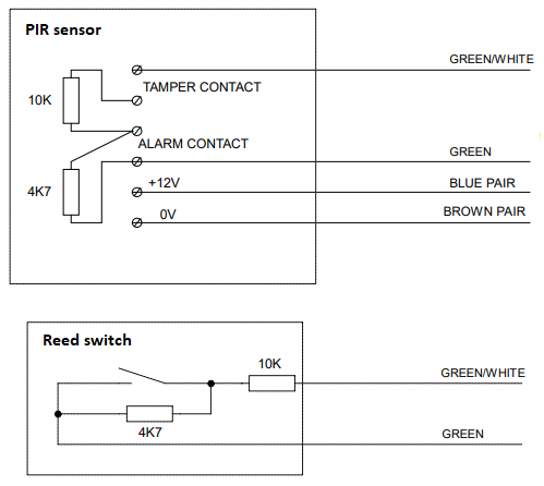
Resistor 1 (10K) is connected in series with the security alarm wiring, and resistor 2 (4K7) is connected across the alarm contact.
The Monimod connects between your sensor and state monitor hardware (e.g. the LSC) and detects changes in voltage on the sensor cable. It translates the different voltage levels to binary signals which are sent to the state monitor via the 4 inputs, where the firmware will generate the necessary security events (see events).
[Sensor] <-----CAT5/6-----> [Monimod] <-----CAT5/6-----> [LSC]
Currently a test version is being producted which is a single inline device, but plans are underway to produce a multi-port device (8 ports, 4-in 4-out) so multiple security sensors can be connected to your state monitor.
The Monimod will detect the following states for a security sensor wired up with EOL resistors;
| State | LCD Display | Description |
|---|---|---|
| Normal | Green | The sensor is in a safe state, e.g. no movement detected or door/window is closed |
| Alarm | Red | The sensor has been tripped, e.g. movement detected or door/window is opened |
| Tamper | Magenta (flashing) | The sensor wiring has been compromised (open circuited), e.g. a sensor cover has been removed or a cable has been cut |
| Short | Magenta (flashing) | The sensor wiring has been compromised (shorted), e.g. intentional attempt to bypass the sensor, or a nail/screw through the cable |
| Fault | Cyan (flashing) | The sensor has been unplugged or a system fault has been detected |
Configuration
The firmware can be configured by publishing an MQTT message to this topic;
[PREFIX/]conf/CLIENTID[/SUFFIX]
where:
PREFIX: Optional topic prefix if requiredCLIENTID: Client id of device, defaults to<MACADDRESS>SUFFIX: Optional topic suffix if required
The message payload should be JSON and it's format is defined in a JSON schema document included in the adoption payload published here;
[PREFIX/]stat/CLIENTID[/SUFFIX]/adopt
See the config value in the /adopt payload.
Default Input Type
By default all inputs are initialised as type switch. Individual inputs can then be configured as required (see below). However it is also possible to change this default. For example, if you are intending to use push buttons throughout your home, instead of setting individual config for each input, you can simply set the defaultInputType to button and be done with it.
| Key | Mandatory | Value |
|---|---|---|
defaultInputType | Optional | Either button, contact, press, rotary, security, switch or toggle |
Examples
To configure the default input type to be button;
{
  "defaultInputType": "button"
}
TIP
You can still override the default input type with specific configuration for individual inputs, see below.
Input Config
Each INPUT can be configured via the following properties;
| Key | Mandatory | Value |
|---|---|---|
index | Mandatory | Index of the input to configure |
type | Optional | Either button, contact, press, rotary, security, switch or toggle |
invert | Optional | Either true or false |
disabled | Optional | Either true or false |
WARNING
Disabling an input will stop any events being emitted!
Examples
To configure input 4 to be a bi-stable switch, input 7 to be an inverted button, and input 8 to be a disabled contact sensor;
{
  "inputs": [
    { "index": 4, "type": "switch" },
    { "index": 7, "type": "button", "invert": true }
    { "index": 8, "type": "contact", "disabled": true }
  ]
}
TIP
A retained message will ensure the device auto-configures on startup.
Recommended Configurations
Below is a table showing possible connected devices and the supported input types. Check marks indicate the recommended configurations to ensure intended behavior.
| Connected Device | button | contact | press | rotary | security | switch | toggle |
|---|---|---|---|---|---|---|---|
| Bi-Stable Switch | ❌ | ❌ | ❌ | ❌ | ❌ | ✅ | ✅ |
| Door / Window Contact | ❌ | ✅ | ❌ | ❌ | ✅ | ❌ | ❌ |
| PIR | ❌ | ✅ | ❌ | ❌ | ✅ | ❌ | ❌ |
| Push Button | ✅ | ❌ | ✅ | ❌ | ❌ | ❌ | ❌ |
| Rotary Encoder | ❌ | ❌ | ❌ | ✅ | ❌ | ❌ | ❌ |
A rotary encoder requires two inputs, and a security sensor requires four inputs. You must configure each of the inputs connected to these devices the same, i.e. both inputs for a rotary encoder should be set to rotary, and all four inputs for a security sensor should be set to security. The status of the device is reported using the index of the last input.
Events
An input EVENT is reported to a topic of the form:
[PREFIX/]stat/CLIENTID[/SUFFIX]
where;
PREFIX: Optional topic prefix if requiredCLIENTID: Client id of device, defaults to<MACADDRESS>SUFFIX: Optional topic suffix if required
The message payload is JSON and contains:
| Key | Value |
|---|---|
port | Port this event occured on (1-32) |
channel | Channel this event occured on (1-4) |
index | Index of this event (1-128) |
type | Event type (see below) |
event | Event (see below) |
| Event Type | Event |
|---|---|
button | single, double, triple, quad, penta, hold, or release |
contact | open or closed |
press | press |
rotary | up or down |
security | normal, alarm, tamper, short or fault |
switch | on or off |
toggle | toggle |
Examples
A contact opening on input 7;
{
  "port": 2,
  "channel": 3,
  "index": 7,
  "type": "contact",
  "event": "open"
}
A triple button click on input 4;
{
  "port": 1,
  "channel": 4,
  "index": 4,
  "type": "button",
  "event": "triple"
}
Index Calculator
Use the index calculator below by selecting the 'Port' and 'Channel' you intend to configure, the calculator will display the 'Index' required in your configuration.
1
Supported Hardware
This firmware is compatible with the Light Switch Controller (LSC) and is designed to run on the RACK32 as part of the OXRS eco-system.
The LSC hardware provides 12V power down the cable, which can be used for powering sensors (e.g. PIRs), or illuminating LEDs.
The sensors or switches should pull one of 4 INPUT wires in the cable to GND to indicate that they have been activated.
The LSC hardware has physical pull up resistors to pull the INPUT wires high and detects when they are pulled low.
The RJ45 pinout for each port is;
| PIN | DESCRIPTION |
|---|---|
| 1 | INPUT 1 |
| 2 | INPUT 2 |
| 3 | INPUT 3 |
| 4 | VIN |
| 5 | VIN |
| 6 | INPUT 4 |
| 7 | GND |
| 8 | GND |
Further Information
Downloads
Download the latest binary of the firmware from GitHub.
Download the source code of the firmware from GitHub.
Flash Binary
How to flash the binary.
Home Automation Integration
Below are some examples of how you could integrate with various home automation systems.
Home Assistant integration examples.
Node-RED integration examples.
Credits
- Jonathan Oxer jon@oxer.com.au
- Ben Jones https://github.com/sumnerboy12
- Moin https://github.com/moinmoin-sh
License
Copyright 2020-present SuperHouse Automation Pty Ltd www.superhouse.tv
The software portion of this project is licensed under the Simplified BSD License. The "licence" folder within this project contains a copy of this license in plain text format.